Table of Contents
MitsuRunner hardware build instructions
There are many ways to build hardware for MitsuRunner. Here is an example how to build it using Wemos D1 Mini Pro.
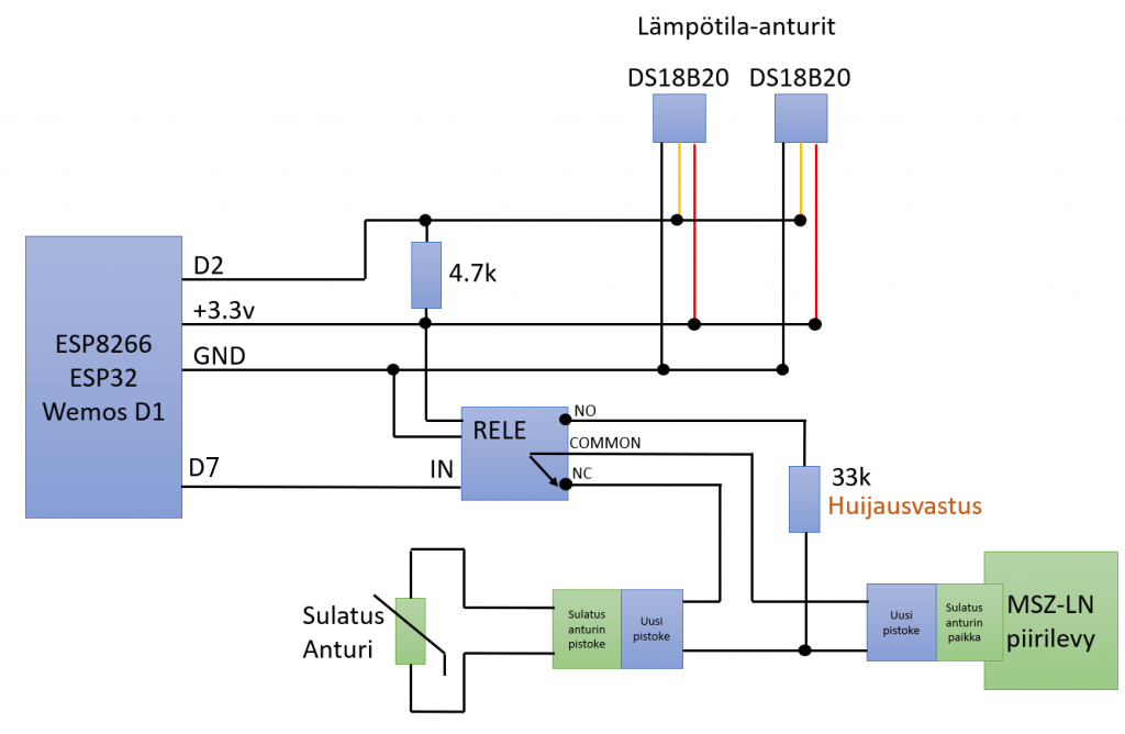
Wiring diagram
English version of the wiring diagram coming in the future, here are finnish-english translations
- Lämpötila-anturit = temperature sensors
- huijausvastus = hack resistor
- sulatusanturi = defrost thermistor
- uusi pistoke = new connector
- sulatusanturin pistoke = defrost thermistor's cable side connector (female)
- sulatusanturin paikka = defrost thermistor's board side connector (male)
- piirilevy = circuit board
Harwdare requirements
- Soldering station / soldering iron
- Solder
- Pliers for cutting
- Ideally heat shrink tube in different sizes
- Wemos D1 Mini (ESP8266; also ESP32 works fine) development board
- Wemos Relay Shield (or any relay compatible with your chosen dev board)
- Connecting pins
- * Normally comes with the Wemos
- 2x Dallas DS18B20 waterproof temperature sensor with ~1m wire (36“ = 91cm is ok)
- 4k7 resistor (4.7k ohms)
- USB power supply for the dev board
- Power socket for the USB power supple (dirty socket: two red round Abikos + 1m wire + two 3-way Wago connectors)
- Enclosure/box for outdoor use.
- * For example ABB IP65 junction box (“jakorasia”)
- * Note: Most likely the 86x86mm junction box is not large enough, 104x104mm or bigger recommended
- Something to drink
Connecting pins
Connect the connecting pins with each other as shown. You need to press a little bit to connect them completely.
Dev board & relay
Take a look on Wemos D1 Mini (or Pro, doesn't matter) and the Relay shield. Both have same pin names written on them. You must install them same so that the names match, only one correct way to do it.
Start soldering. A good temperature is around 290°C (depending on your solder). If you never solder such small devices, look for an old defective radio, television, whatever and practice first.
Solder point by point. Ensure by 100% that there are NO bridged connections between the neighbouring pins. For example D1 and D2 are NOT connected by mistake by using too much solder.
4k7 resistor & temperature sensors
Next, take 4k7 resistor. If any doubts check the resistance with a multimeter: Set to resistance mode and measure across the sides. If it shows 4.7k, perfect. Even 4.67k or 4.73k is okay, there is always a small difference for measuring and tolerance.
You also can read the resistance by the colored rings on the resistor as long as you read the correct. https://www.digikey.com/en/resources/conversion-calculators/conversion-calculator-resistor-color-code-5-band
On D1 Mini ESP8266 we shall use pin D2 for temperature sensors. You can also use D5, D6 or D7 (or even D1 if you connected the relay to other pin; D1 Mini Relay Shield defaults to D1 pin). In EPS8266 other pins have special functions which can/will cause problems. Write down the pin number as you will need it later.
So solder the 4k7 resistor to D2 and 3.3V. Once soldered shorten the legs with pliers.
Lastly solder DS18B20 sensors' black wire to ground GND, red wire to 4k7 resistors' 3V3 side and third wire (data) on 4k7 resistors' other side which connects to one D data pin.


