MitsuRunner HW istallation instructions
There are many ways to build Hardware for MitsuRunner. Here is an example how to build it using Wemos D1 Mini Pro.
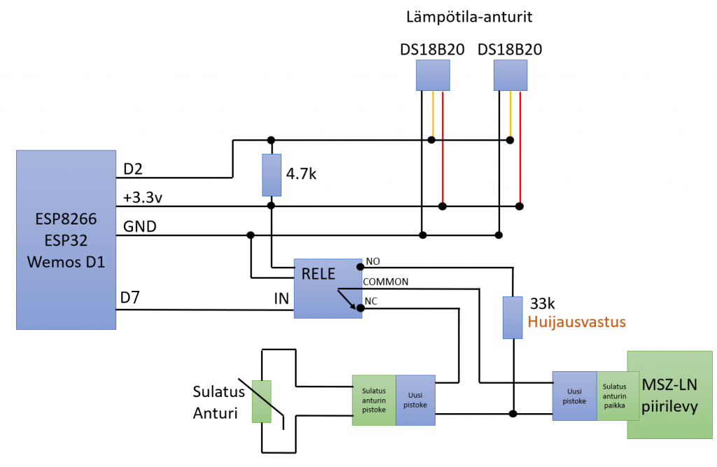
Wiring diagram
English version of the wiring diagram coming in the future, here translated:
- lämpötila-anturit = temperature sensors
- huijausvastus = hack resistor
- sulatusanturi = defrost thermistor
- uusi pistoke = new connector
- sulatusanturin pistoke = defrost thermistor's cable side connector (female)
- sulatusanturin paikka = defrost thermistor's board side connector (male)
- piirilevy = circuit board
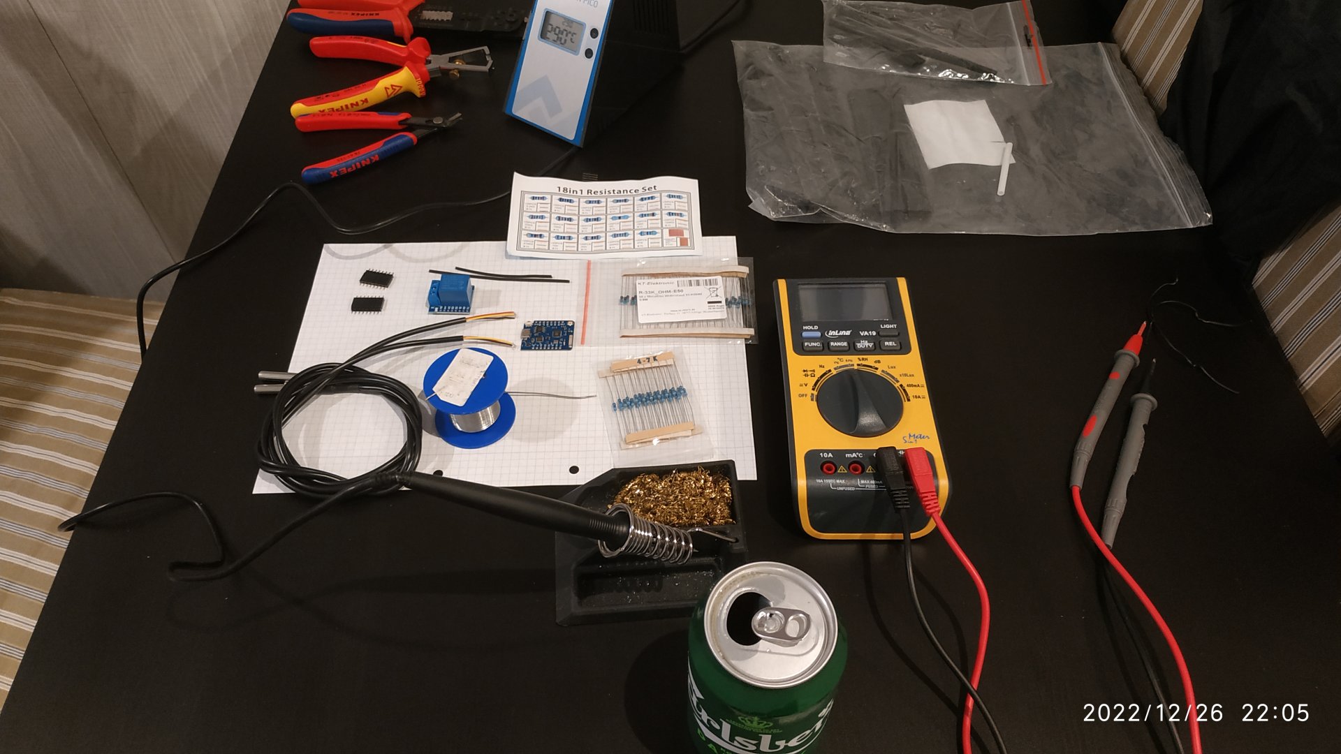
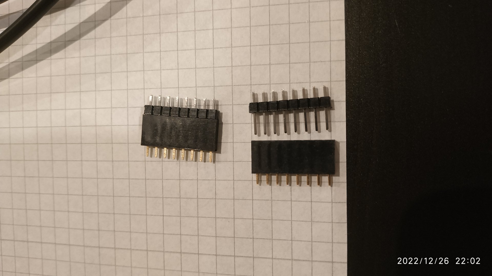
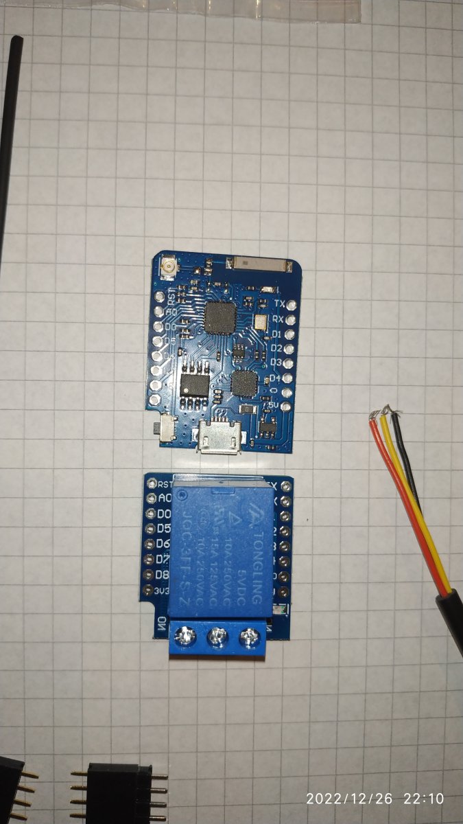
So, here we go: Picture 1 & 2: Here is everything, we could need.
- Different pliers
- Soldering station / soldering iron
- Solder
- 4.7k resistance
- Wemos D1 Mini
- Wemos Relais
- Connecting pins (normally delievered with the WEMOS)
- 2x DS18B20
- Ideally heat shrink tube in different sizes
- Something to drink
Picture 3: Connect the connecting pins as shown with each other, you need to press a little bit, to connect them completely!
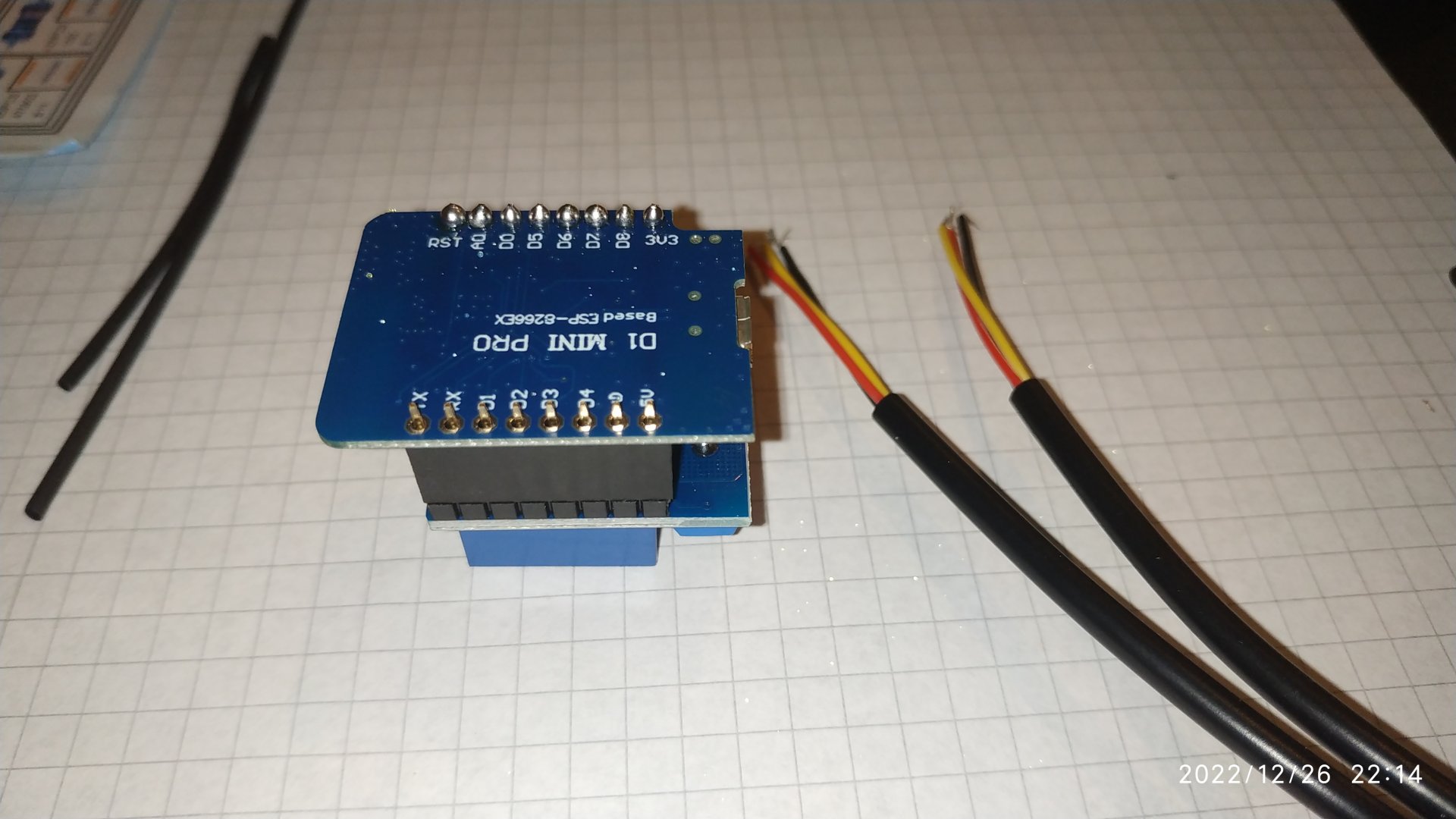
Picture 4: Just check your Wemos D1 Mini (or pro, doesn't matter) and the relais properly. Just in ONE specific position, the contacts fit together. For example: TX to TX, RX to TX, D1 to D1, D2 to D2, GND to GND (or G), 3V3 to 3V3. Just already check now, and remind, that you need to solder it together in such a way, that there are NO mixed connections (for example RST to TX etc.. That will NOT work and may damage the board!
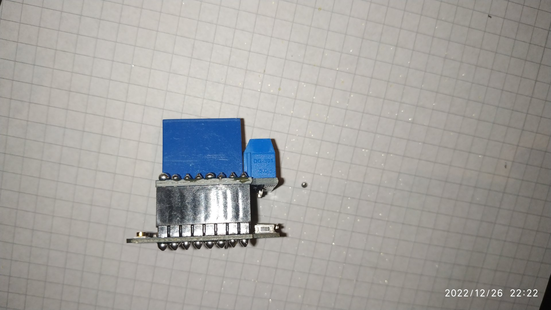
Picture 5, Picture 6: Start soldering. If you never did on such small devices, look for an old defective radio, television, whatever and make there some trials at first. Solder point by point and ensure by 100%, that there are NO connections between the neighbored things (for example, that D1 and D2 are NOT connected by mistake, by using too much solder). A good temperature for doing it, is around 290°C (depending on your solder).
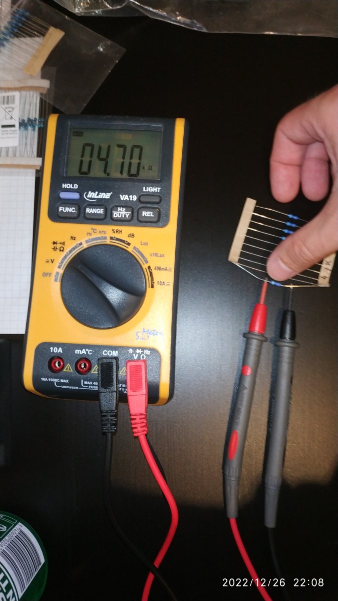
Picture 7: All done? Good boy! Next, take your resistor and / or if you are not sure, check the resistance with a multimeter as shown. Set it to the resistance mode, connect the cable properly and measure between and after the resistance. If it shows 4.7k, perfect. Even 4.67k or 4.73k is okay, there is always a small difference for measuring and tolerance. Just ensure always, that it is 4.7k in the end (4700 Ohm). You also can read the resistance by the colored rings on the resistor, just google for it, how the colored rings are counted.
Picture8 and Picture 9:
TODO CLEAR UP THIS PIN NUMBER PART
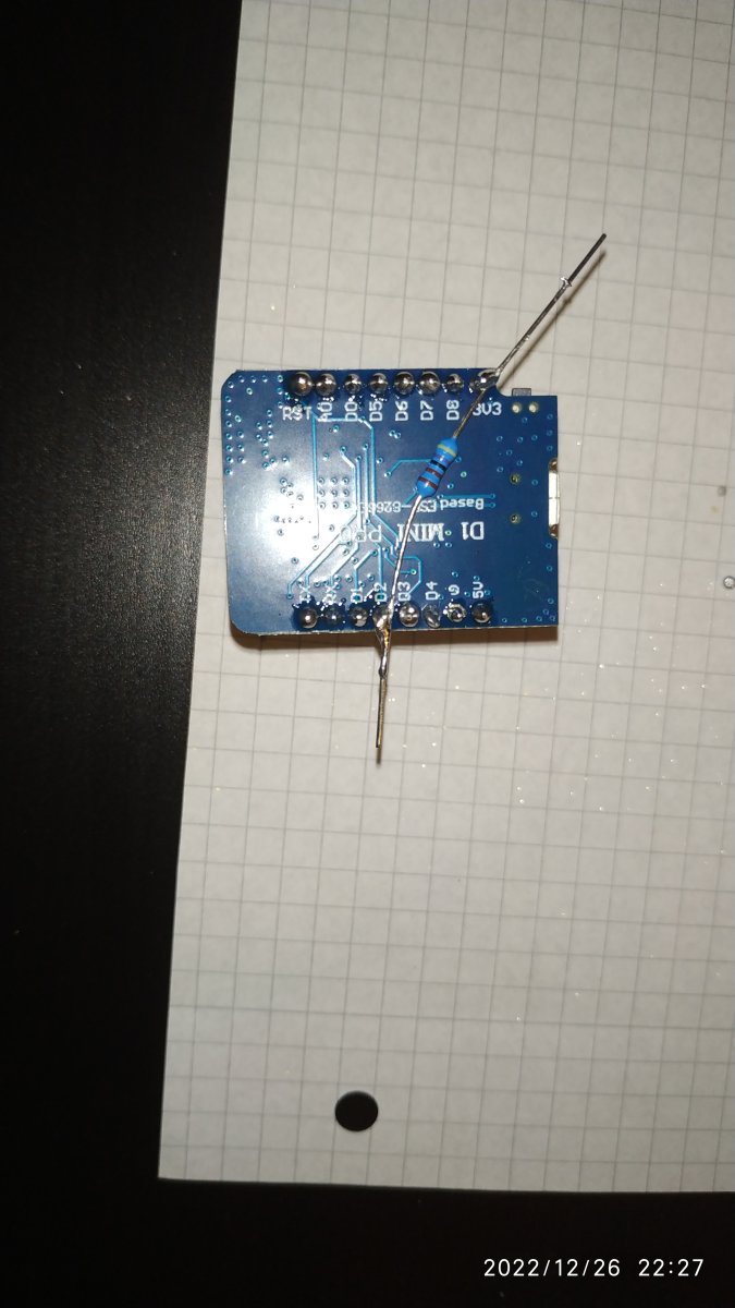
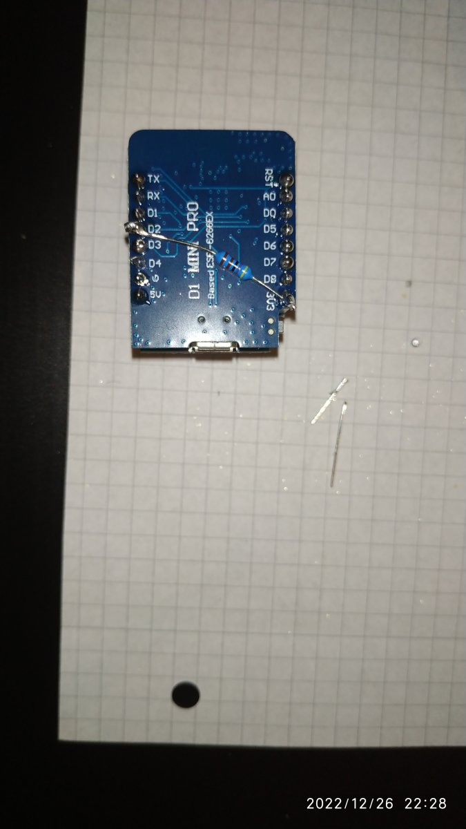
As shown in the wiring diagram, now solder the 4.7k resistor between D2 and 3.3V, at the end, shorten the wire with the pliers. I have seen here in this board several versions, where it was (by my wemos-layout) soldered between 3.3V and D7, so I was a bit confusing, why it looked so different.
The truth is, there are different layouts of this board and you can solder this connector also between other 3.3v and D connectors, just DON'T use connector DX DX (the pro's, please help me with the numbers, which D connectors weren't possible, I will edit this post!). !!!The only important thing is, to remember to which D connector you soldered this resistance, you need to edit this one later in the mitsurunner software, otherwise it is NOT going to work!!! Remember AND make a note for yourself!!! D2 and 3.3V is always a good choice!